Microns, Magnets and Copper: How Robots Build the Motors That Drive Electric Cars
Hairpin stators, magnet-loaded rotors and monitored fastening each need tight control. The air gap between rotor and stator ties the whole process together, and most speed and yield claims come from equipment makers.
An electric car’s motor is simple in principle, a stator and a rotor separated by a very small gap, but building it at volume is demanding. A review in the journal Energies says end-of-line test outcomes are strongly shaped by the tolerances of structural parameters, including stator inner and outer diameters, magnet dimensions and air gaps. Robots and automated machines are used at each stage to hold those tolerances.
Stator: Placing Hairpins Without Damaging Insulation
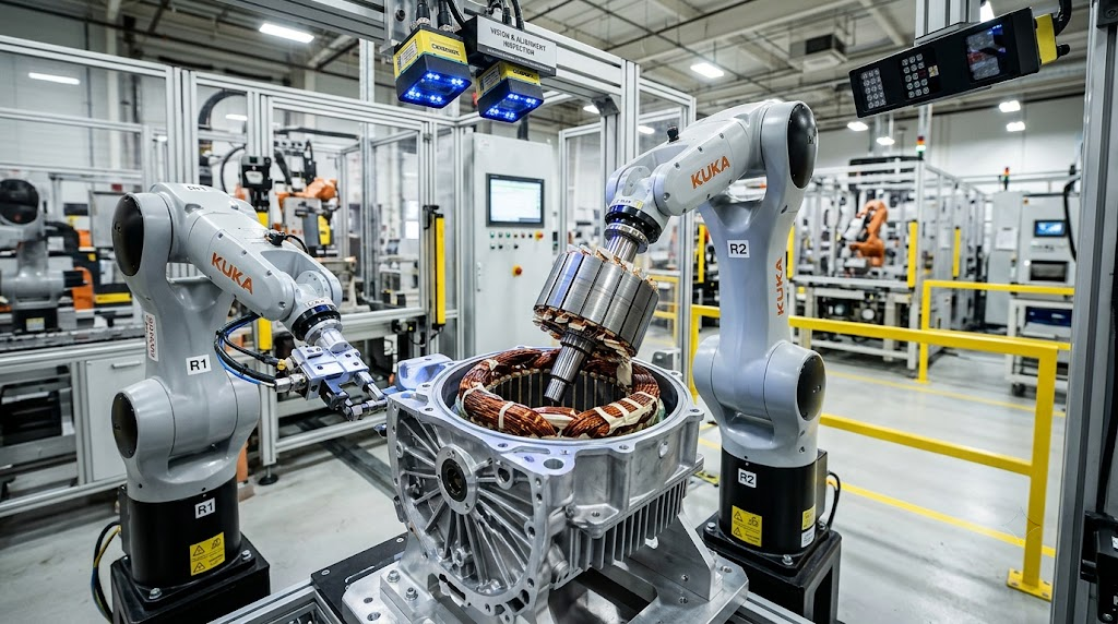
Many EV stators use rectangular copper “hairpins.” The equipment maker Honest-HLS describes the sequence as hairpin forming, insertion, twisting, welding and inspection. Its insertion machine places slot liners and inserts wires in layers using servo-controlled force feedback, and expands the wire slightly to protect the insulation. The company says one line it built handles a 48-slot, 12-layer stator in a 45-second cycle. That is a vendor figure.
Quality control starts early. ZEISS notes that hairpins are highly susceptible to deformation and that their ends are difficult to weld, so their dimensions and positions must be checked during stator assembly.
Rotor: Taming Powerful Magnets
Rotors present a different problem. An E-Mobility Engineering feature on production technology says interior permanent magnet rotors are stacked from laminations, then magnetized in a high-energy fixture. The rotor stack is shrunk onto the shaft by heating the core and cooling the shaft with liquid nitrogen. Because traction motors can run at 16,000 to 20,000 rpm, the assembly is dynamically balanced.
Handling magnets is tricky. A patent for a magnet gripper says placing many magnets is difficult because of the precision needed and the magnetic attraction to the core and to magnets already in place. GROB, a motor-line builder, offers robotic magnet insertion that it says flexibly handles different rotor shapes, along with shaft fitting with force and position control. Kinemetrix, an integration firm, adds that rotor magnets are small, easily damaged and vary in size, and that bonding them with two-part adhesives needs tiny dispense volumes, tight mix ratios and nozzles that clog quickly.
Automated Fastening: Torque Is Not Enough
Housings and end-shields are closed with threaded fasteners. Kinemetrix describes servo-driven screwdriving heads that monitor torque, turns and distance as they drive each fastener. In a BMW axle-production report, a BMW engineer said standard torque wrenches confirm a minimum torque was reached but leave overtightened screws undetected, and BMW’s monitoring stores each tightening result with Newton-meter and angle accuracy.
Data volume is a challenge. A 2026 peer-reviewed paper from TU Dresden in Procedia CIRP says traditional control windows on torque and angle signals can miss anomalies or faulty screw connections. It proposes a hybrid machine-learning method that needs only 20 training curves to set up.
Tolerances: Why the Air Gap Rules
The Energies review says a larger air gap lowers power density and torque and raises magnetic reluctance. A smaller one raises the risk of mechanical interference, vibration and magnetic saturation. Deviations in stator inner diameter translate directly into air-gap variation.
Operating heat matters too. A February 2026 PLOS ONE study analyzed a permanent-magnet motor whose tolerance design proved inadequate because of temperature rise in operation, and modeled how thermal deformation changes assembly error. E-Mobility Engineering also notes that a carbon-fiber sealing tube in the air gap must be very thin, or it widens the gap.
Testing Before the Motor Leaves the Line
Testing closes the loop. Honest-HLS describes end-of-line stator checks covering surge, resistance and partial discharge, plus dimensional measurements. AVL’s test-systems manager told E-Mobility Engineering that a piezoelectric sensor setup measures reaction forces and torque during a 30-second acceleration, taking one to two minutes to attach the stator and test, compared with about five minutes for older load-based machines.