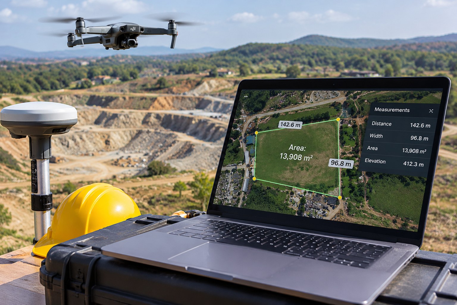
Open a drone orthomosaic on a large monitor and it can be tempting to start measuring straight away. A roof edge looks crisp, road markings are clear and the site boundary seems obvious. The software may even return a measurement to two decimal places. None of that, by itself, proves the number is right. A useful-looking picture and a defensible survey measurement are two different things.
This article focuses on what makes a distance or area measured from drone imagery dependable—not on how to plan a general mapping mission.
Start with scale: what does one pixel represent?
Ground sample distance, usually shortened to GSD, gives you a sense of image scale. If a dataset has a GSD of 2 cm, each pixel represents roughly a 2 cm patch on the ground under the stated capture geometry. A feature spanning 100 pixels would therefore be about 2 metres long in the image. Useful to know—but it does not mean the feature has been measured to within 2 cm.
That is a sampling scale, not an accuracy certificate. A 2 cm GSD does not mean every measurement is accurate to 2 cm. Edge definition, camera calibration, overlap, viewing angle, surface texture, georeferencing and control quality all affect the final result. USGS warns against assigning accuracy simply because a dataset has a small GSD. [1]
Ground reference: how does the model know where it is?
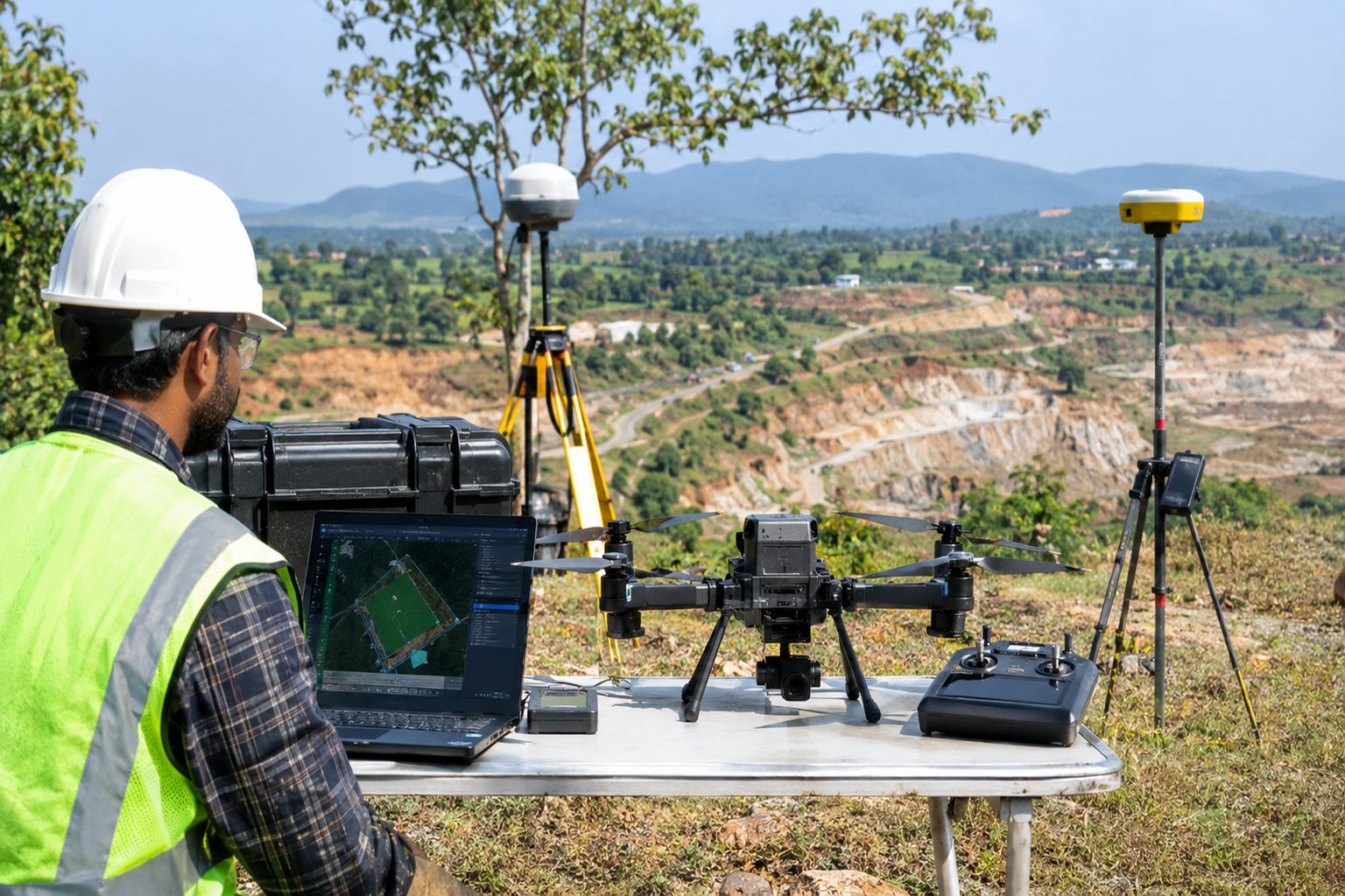
Ground control points (GCPs) are visible targets whose coordinates are measured on the ground using survey-grade GNSS or a total station. Photogrammetry software uses these coordinates to constrain the model and tie it to a real-world coordinate system. [1][2]
GCPs should be easy to identify, stable, accurately surveyed and spread across the project. If every control point is near the centre, the model may fit there but behave less reliably near edges or elevation changes. Poorly measured control can limit the accuracy of the whole output. [1]
RTK or PPK image positioning can reduce the number of GCPs needed in some workflows, but it does not eliminate quality assurance. Camera positions still depend on a correctly established reference and suitable GNSS observations. Independent checkpoints remain essential for testing the final result. [2][3]
Image quality changes what can be measured
Sharp images make it easier to identify a wall corner, road marking or target consistently across several photographs. Blur, glare, shadows, low contrast, repeated patterns, moving vegetation and reflective surfaces make matching points harder. Weak overlap or inconsistent exposure can also reduce reconstruction stability. [1][4]
Consider a boundary wall partly hidden by tree branches. The orthomosaic may look attractive at normal screen size, but the actual wall edge is uncertain because the photos do not show a stable, clear feature. Tracing a line to the nearest shadow creates a precise-looking measurement from the wrong reference.
Independent checkpoints: the test that matters
Here is the important distinction: a checkpoint is not used to help the software build the map. The surveyor measures it independently on the ground, leaves it out of processing, and then checks where it appears in the finished model. The difference between those positions gives a fairer test than simply checking the control points used to create the map. [1][2]
Do not report residuals of GCPs used to fit the model as independent proof of accuracy. A model can fit its own control points closely and still have systematic errors elsewhere. Checkpoints are held out during processing and used afterwards to validate the product. [2]
Spread checkpoints across the site and, where relevant, across different elevations and surface types. Report the number of checkpoints, survey method, distribution, horizontal and vertical errors, and statistic used (such as RMSE). A single convenient point cannot characterise a large or uneven site.
Simple example: measuring a warehouse roof
Imagine a contractor asking for the length of a warehouse roof. The mapping software reports 48.26 metres. It looks precise, but the two decimal places are only how the software displays the answer. They do not tell you whether the roof edge was identified correctly or whether the map is positioned accurately.
If the map has 2 cm GSD, roof corners are sharply visible, control targets are well distributed and independent checkpoints show small, consistent residuals, the surveyor can report 48.26 m alongside the project’s measured accuracy and method. If the roof edge is hidden or checkpoints show a systematic shift, the same displayed number is not defensible. A field measurement or total-station check may be needed.
What to ask before trusting a drone measurement
What is the GSD, and at what flight height and camera configuration was it achieved?
Which coordinate reference system and vertical datum were used?
Were GCPs used, how accurately were they surveyed and how were they distributed?
Were separate checkpoints held out from processing? How many and where?
What are the horizontal and vertical RMSE or other reported error statistics?
Were blur, poor overlap, shadows, reflective surfaces or vegetation identified as limitations?
Is photogrammetry suitable, or is a total station, GNSS rover or direct field measurement required?
When should you not rely on the photo alone?
Do not use a drone image as the sole basis for legal boundary determination, high-value payment quantities, safety-critical clearances or engineering tolerances unless the survey method, validation and professional requirements support that use. A photo can help identify where to measure; it does not automatically replace a cadastral survey or site instrument measurement.
The takeaway
Think of the orthomosaic as the picture you can measure from, not proof that every measurement is correct. GSD tells you the pixel scale; control points help anchor the model; image quality affects how clearly features can be reconstructed; and independent checkpoints show how well the finished result agrees with the ground. If a supplier cannot explain those checks, ask for more evidence before using the number for a contract, design or safety decision.